Welcome to Winner Ball Valves Co., Ltd.
E-mail: webmaster@winner-hvac.com TEL:0086-731-82788880 | Chinese


AK...Series Air Damper Actuator
Air Damper Actuator
Classification:
Air Damper Actuator
Product Description
FUNCTIONS & FEATURES
a. Make a turn actuated by electric signal(e.g. From HVAC) within 0-90 ( 93 mechanically) .
b. Angle of rotation can be set freely .
c. Universal coupling is fit for round shaft from 10...18mm in diameter and square shaft from 6...12 mm.
d. Auto/manual switch which can be transferred freely.
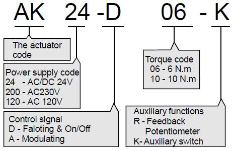
MODEL NUMBER DESCRIPTIONS
TECHNICAL DATA
| Model | AK200/120/24-D06 | AK200/120/24-D10 | ||||
| Output torque | 6 N.m | 10 N.m | ||||
| Power supply | AK200... | AK24... | AK120... | |||
| AC230V | AC/DC24V | AC120V | ||||
| Run time | 30...150s | 30...120s | 30...150s | |||
| Operating power | 12VA,3W | 5VA,3W | 12VA,3W | |||
| Standstill power | 12VA,3W | 5VA,3W | 12VA,3W | |||
| Output angle | 90 (95 Max) | |||||
| ON/OFF control signal | 1 wire or 2 wire control | |||||
| Feedback signal (TF/TS...P) | 10k ohm Potentiometer (1W) | |||||
| Modulating control signal 1 | DC0(2)...10V (100k ohm) | |||||
| Modulating control signal 2 | DC0(4)...20mA ( 500 ohm) | |||||
| Modulating feedback signal | DC0(2)...10V | |||||
| Auxiliary switch (TF/TS...S) | 3A,AC250V | |||||
| Protection class | IP54 | |||||
| Ambient conditions | -10...+55 C 0...90% RH | |||||
| Noise max | 40dB(A) | |||||
| Weight 600...900g | 600...900g | |||||
WARNING
1. Installation are for use by qualified personnel only.To avoid injury and electric shock, do not perform any servicing other than that contained in this manual.
2. All actuators are shipped from the factory ready for installation; no electrical adjustments are required before placing them in operation.
3. Check the connections before energizing the power supply since wrong connections can damage the equipment.
4. The actuator should be stored in its shipping carton in a clean, dry area.
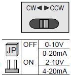
DIRECTION & CONTROL SIGNAL
The rotation can be reversed by pushing the CCW/CW switch on the casing.
To change the input/output signal valve, open the casing and find the JP plug on the PCB. The contro signa valve can be changed by connecting the plug.
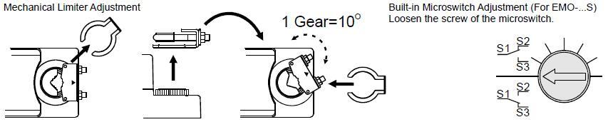
LIMITS FOR ROTATION
INSTALLAION
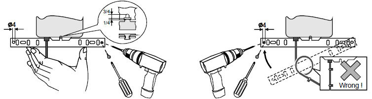
The actuator is suitable for circular spindle of 10 -18mm, or square spindle of 6 -12mm,length>40mm. Procedure :
1. Set the damper at fully closed position. Turn the actuator to the corresponding fully closed position (press down the off-load push-button, turn the spindle connector manually).
2. Place the drive socket of the spindle connector onto the spindle of damper. Set the proper position, then tighten the 2 nuts of the spindle connector.
3. Bend the mounting bracket to the suitable shape and fix its position with screws. (Leave some space between the actuator and the bracket so as to eliminate centering issue).
4. Press the off-load pushbutton, manually turn the damper from fully closed to fully opened position freely and evenly.
5. Connect the wires according to the wiring diagrams on the casing. Make sure the lead wires, and signal wires are connected correctly.
WIRING DIAGRAMS
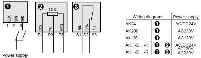
As product improvement is ongoing, this wiring diagram is only for reference.
Detailed wiring diagram is shown on each product casing and should be referred to.
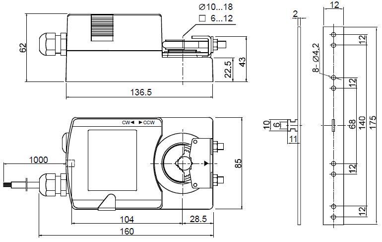
DIMENSIONS
Previous Page
Winner Ball Valves Co., Ltd.
FOLLOW US

National service hotline